
Volvo Instrument Cluster Repair
4/16/2012
Dmaxallitech (Eric) posted a procedure for repairing flaky broken solder joints in a Volvo Instrument Cluster.
The following is excerpted form his original Forum post.
 |
Start by removing the dash cluster from the truck and find your self a nice work area. |
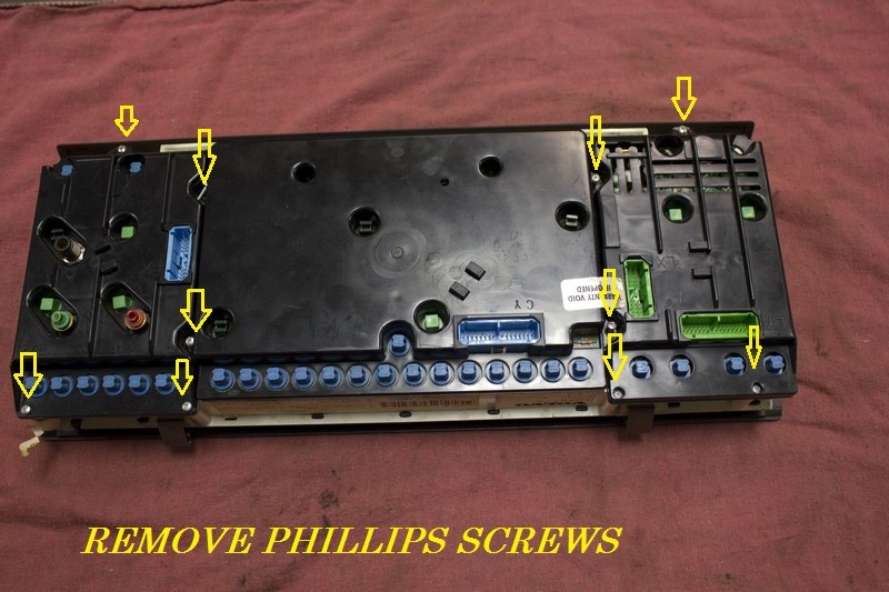 |
Next flip it over so we an start the tear down. Remove Phillips screws. |
 |
Now pull the rear cover for the left side gauge pack ( remember its upside down) |
 |
Now remove the center gauge cluster. Pay attention to the details in the pictures to prevent damage |
 |
Finally remove the right side cover. |
 |
Be carefully when separating the right side circuit board from the housing.
Be careful of the LCD Display connection. |
 |
This screw needs to be removed in order to access the center circuit board. It's in between the tach and the speedo. |
 |
They are only a friction fit. |
 |
If you look closely at the solder joints on the board opposite of the electrical connections you disconnected to remove the cluster from the dash, you will find many broken solder joints. Iys tough to see, but you can identify them by the dark circle at the base of the pin. That is the crack causing the intermittent connection and various dash concerns. |
 |
Another look at the broken solder joints. |
 |
Using a Weller soldering station to remelt the joints with just a dab of solder to make it flow. Very little filler solder will be needed here. Be sureto check all the solder joints carefully. The ones to look at the closest are where the connector bodies are soldered to the boards, four in total |
| Be careful of the LCD Display connection. This screw needs to be removed in order to access the center circuit board. It's in between the tach and the speedo. In order to separate Tach/Speedo, use a small screwdriver and slowly work the gauges off the circuit board evenly. They are only a friction fit. If you look closely at the solder joints on the board opposite of the electrical connections you disconnected to remove the cluster from the dash, you will find many broken solder joints. Iys tough to see, but you can identify them by the dark circle at yhe base of the pin. That is the crack causing the intermittant connection and various dash concerns. Another look at the broken solder joints. Using a Weller soldering station to remelt the joints with just a dab of solder to make it flow. Very little filler solder will be needed here. Be sureto check all the solder joints carefully. The ones to look at the closest are where the connector bodies are soldered to the boards, four in total
Now reverse the disassemble to put it together. |
|